Why Create Connection Methods
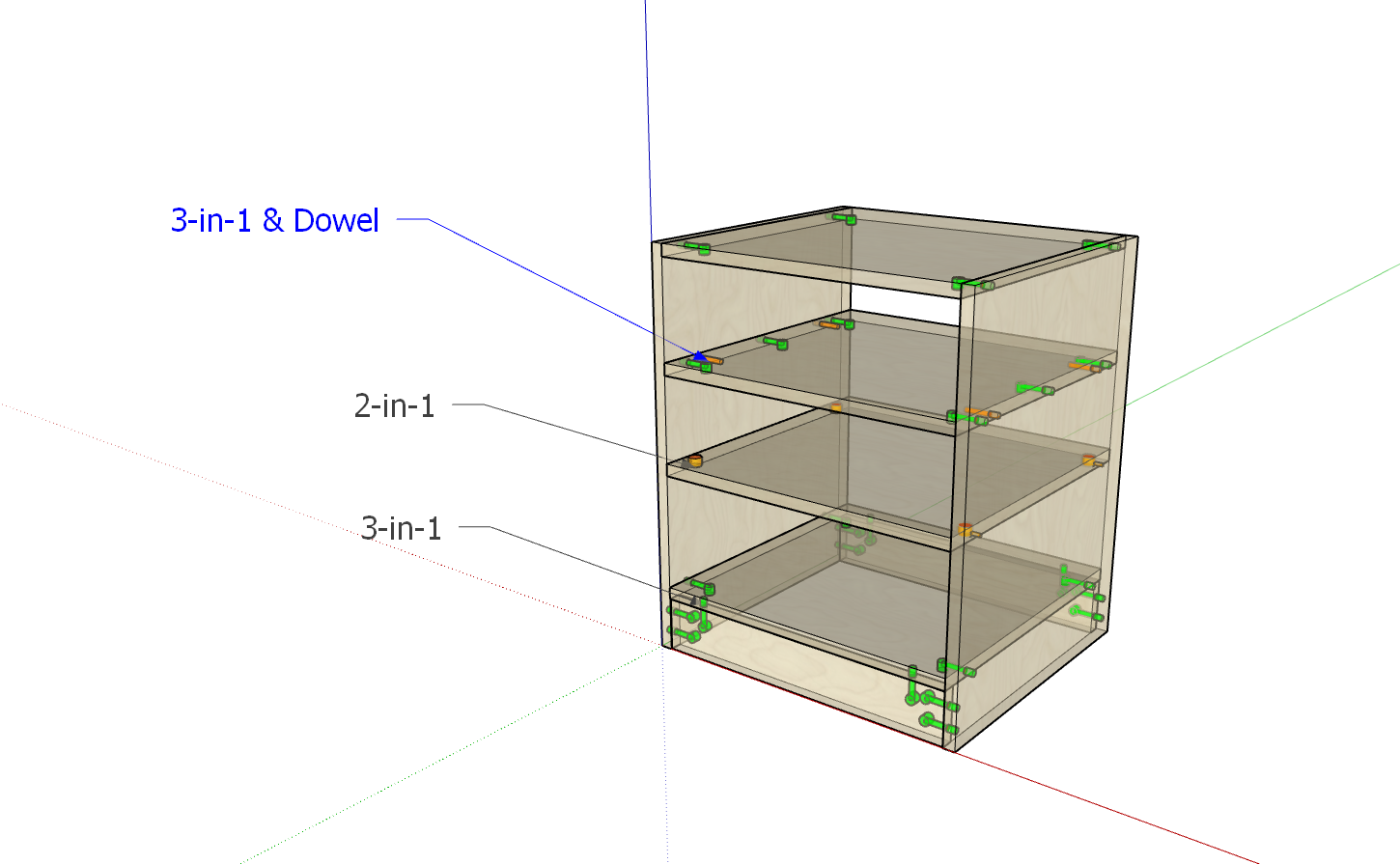
In Beginner Tutorial 3, we created hardware connectors. Once we have connectors, what rules should we use to distribute these connectors on panels with different distances and dimensions? As shown in the figure below: the number of hardware components and connection methods used between panels vary. Moreover, each company has its own set of rules. To meet this diverse need, we designed the connection method functionality.
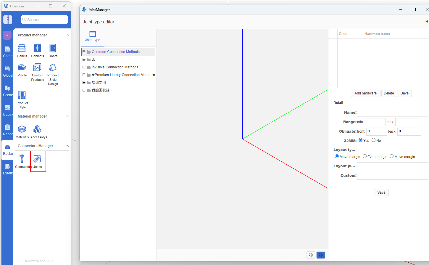
Opening Connection Method Manager
- Open the Zhumu Cloud Platform and click the icon shown below
Creating Connection Methods [Using 32mm System & Dowel as Example]
-
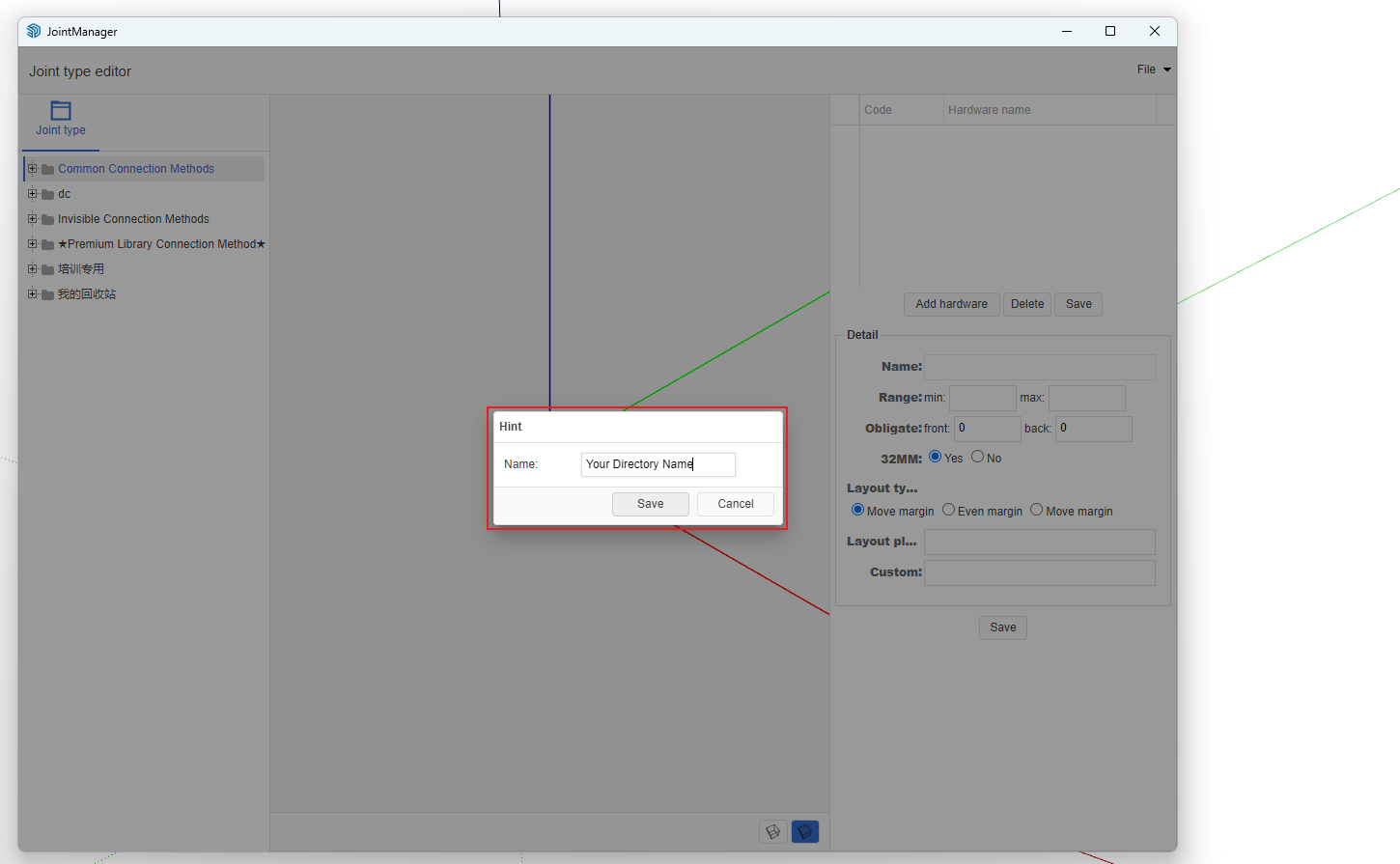
Create your own directory folder
- In the right list, click any node -> Right-click menu -> Add Category

- Enter the category name [Zhumu recommends using your company name]
-
Add Connection Method
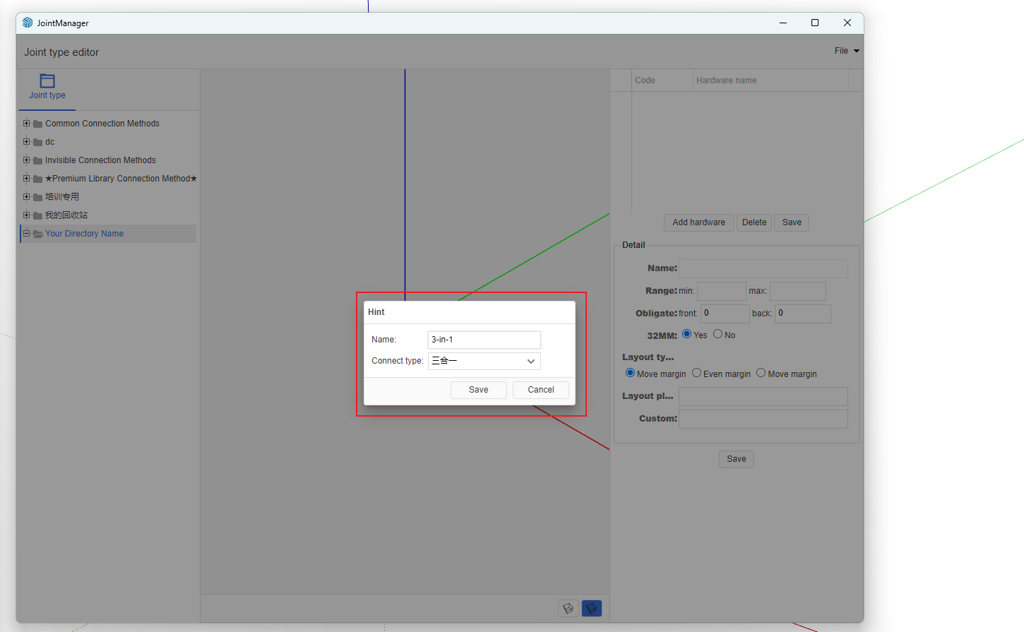
- Click the created category node -> Right-click menu -> Add Connection Method
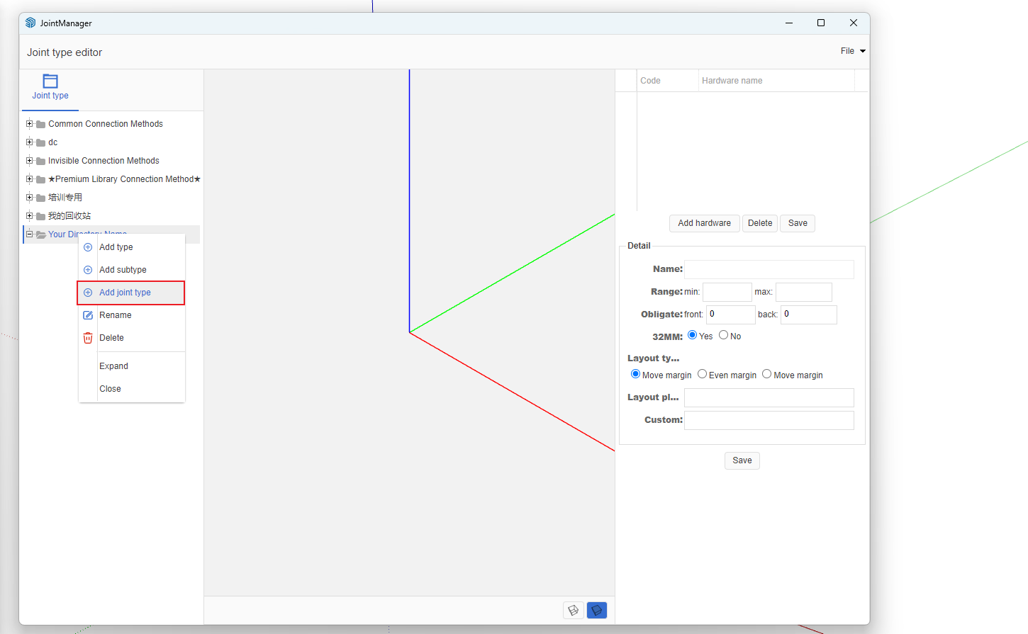
- A dialog box will pop up; enter the connection method name [using 32mm system & dowel as an example]. After entering, click OK.
-
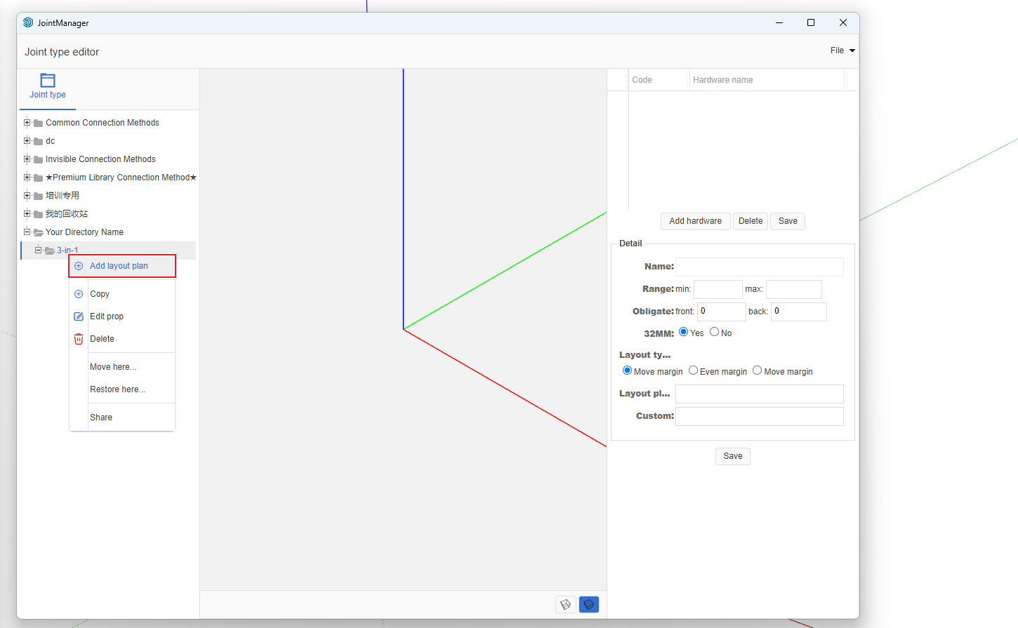
Add Layout Scheme
- Click the name node of the connection method just created -> Right-click menu -> Add Layout Scheme
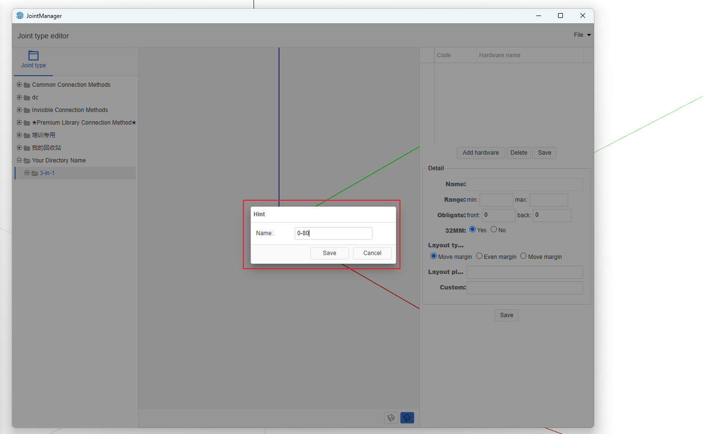
- In the pop-up dialog, enter the scheme name [We recommend using spacing as the scheme name]. After entering, click Save.
- Add Hardware to Layout Scheme
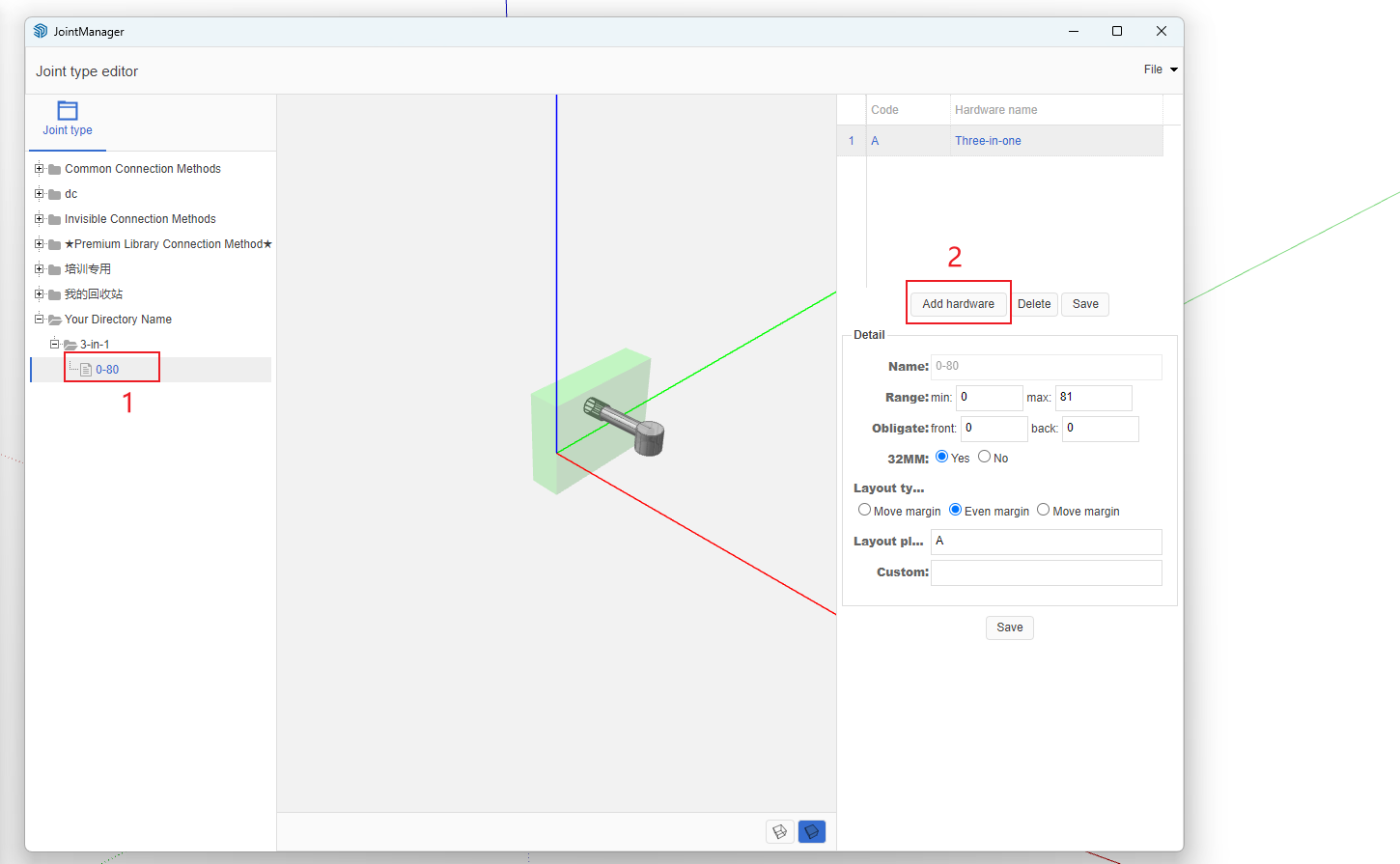
- Select hardware. According to the prompt above, add both 32mm system connector and dowel to the current scheme.

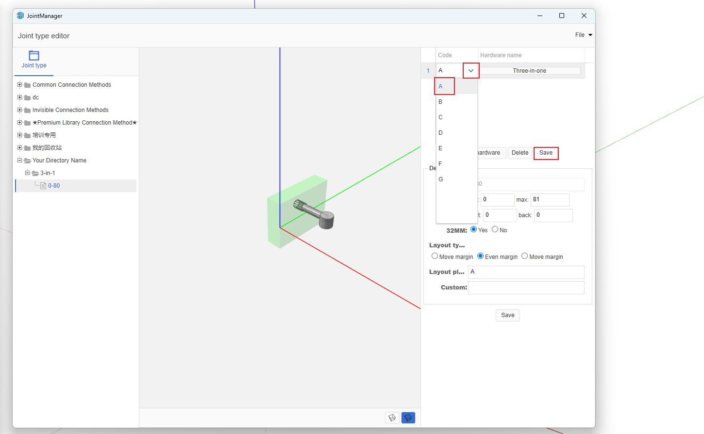
- Modify Hardware Codes
- Edit Scheme Details
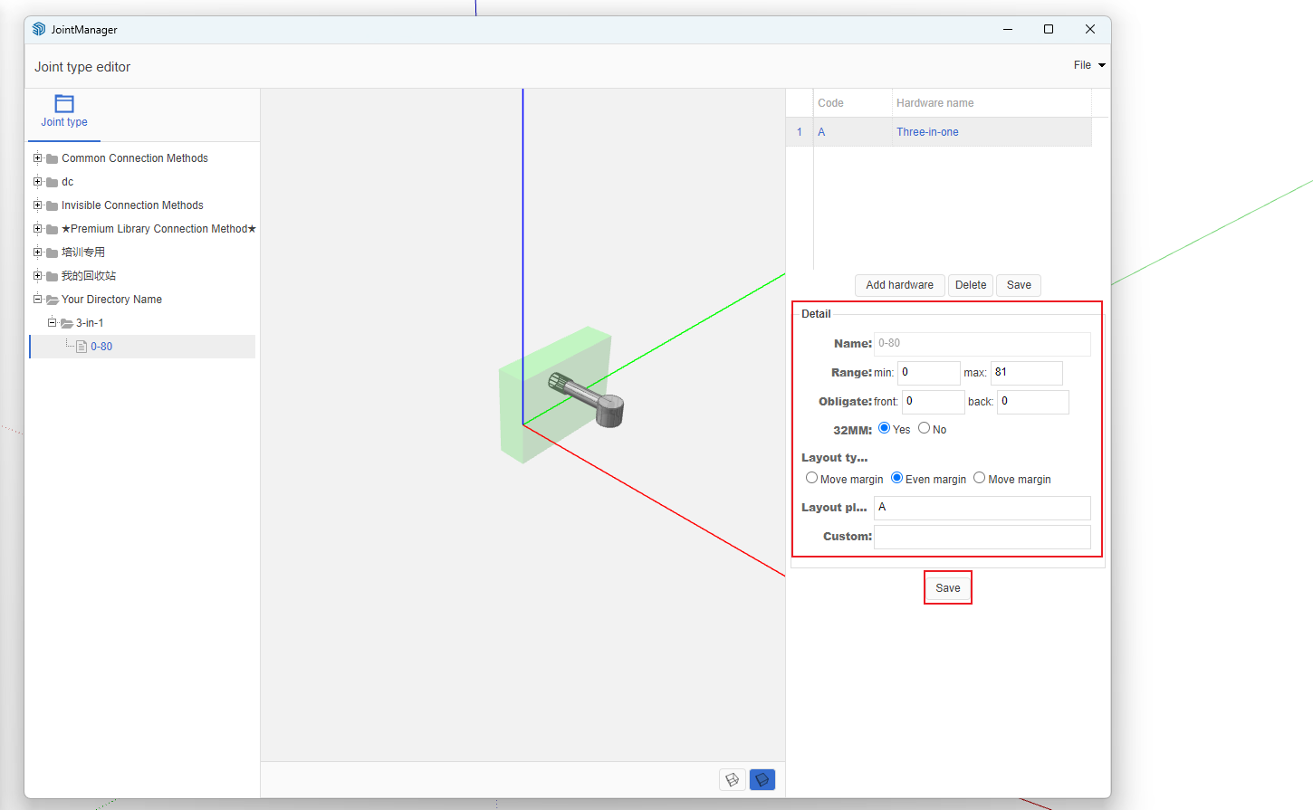
- Scheme Details Explanation
- Range: Define minimum and maximum values. Panels with dimensions greater than or equal to the minimum and less than the maximum will use this layout scheme.
- Front Margin and Rear Margin: Reserve certain dimensions at the front and rear of the hardware layout hole positions.
- 32mm System: Default is Yes, which is very convenient for users who manually drill holes.
- Layout Method: How to distribute the remaining space. After calculating the connector positions, this determines whether leftover space is placed at the front, rear, or evenly distributed.
- Layout Scheme: Write the scheme based on hardware codes. For example: AB represents: 32mm system connector and dowel, with 32mm distance between the two connectors (hole spacing). If it's A*B, it means the dimension between the two hardware components is adaptive.
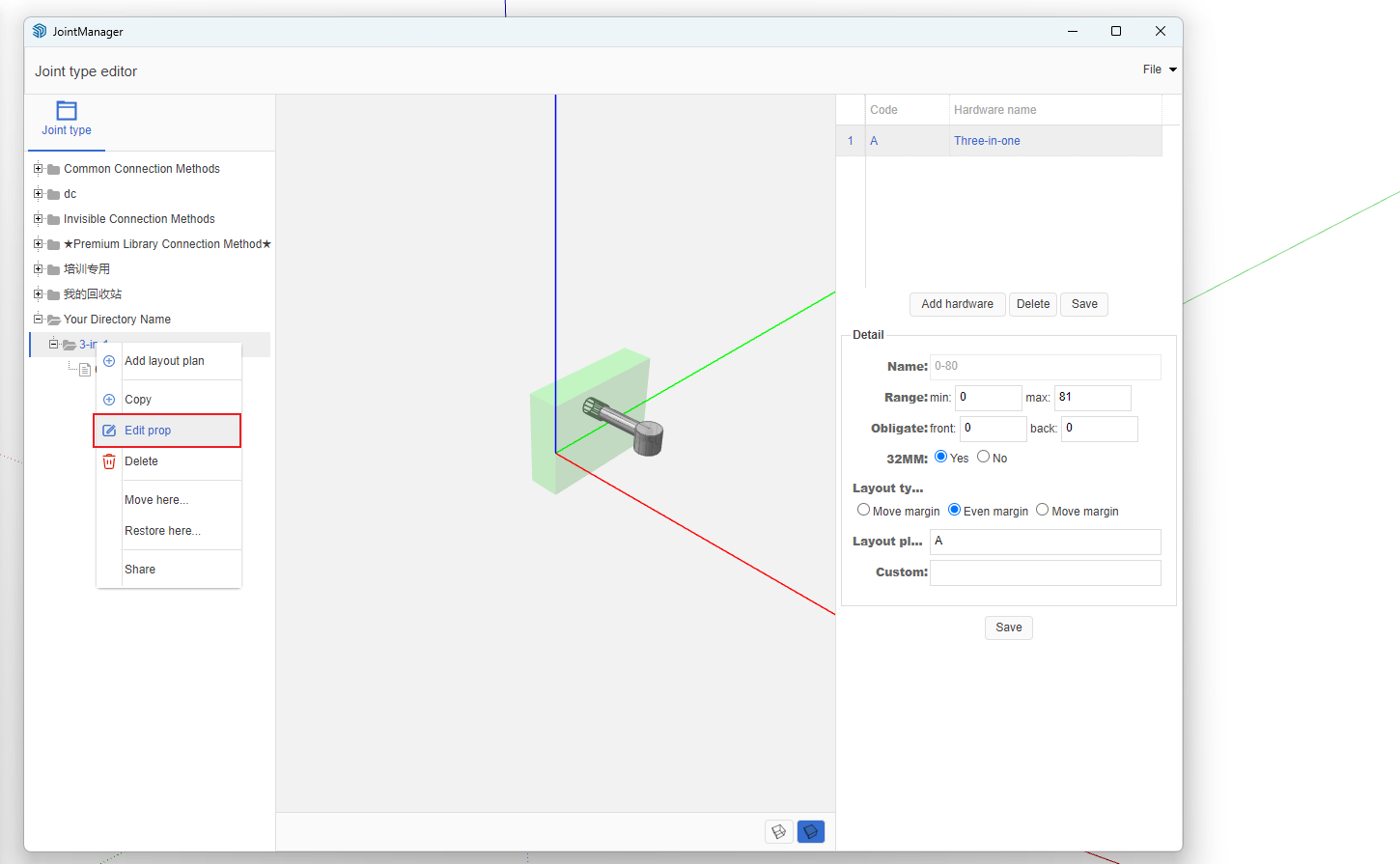
Important Note!!!
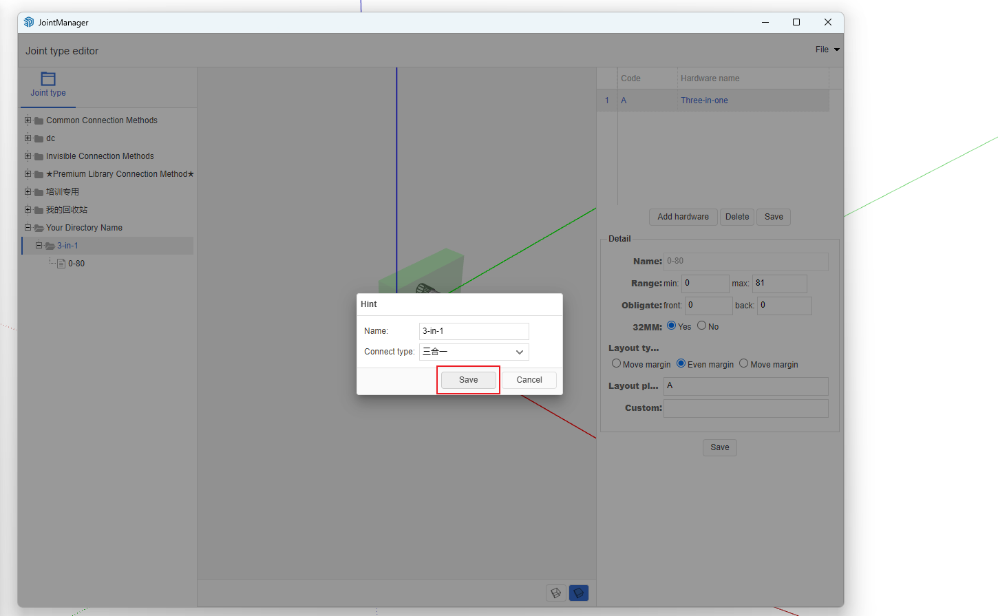
- After each modification to the layout scheme, you must right-click on the parent node of the layout scheme, modify properties, and update according to the connection method attributes. This ensures the backend cache is updated.
- Detailed Video Tutorial